

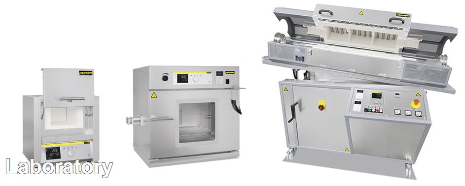
ผู้ผลิตเตาเผา เตาหลอม เตาสำหรับทดสอบขี้เถ้า (Ash Content Testing) สำหรับห้องแล็ป และเตาเผา เตาหลอมอุตสาหกรรมสำหรับการผลิตแก้ว เซรามิกส์ พลาสติก โลหะ เป็นต้น สามารถควบคุมอุณหภูมิในช่วง 30-3000 องศาเซลเซียส มีให้เลือกใช้หลากหลายขนาด
 คลิ๊กด้านล่างเพื่อดูข้อมูลสินค้าเพิ่มเติม
- Muffle/Preheating/Ashing Furnaces and Accessories
- Assay Furnaces up to 1300 °C
- Chamber Furnaces for Annealing, Hardening and Brazing
- Chamber Furnaces with Brick Insulation or Fiber Insulation up to 1400 °C
- High-Temperature Furnaces/Sintering Furnaces
- Ovens and Forced Convection Chamber Furnaces
- Clean Room Solutions
- Tube Furnaces and Accessories
- Customized Tube Furnaces
- Working Tubes for Tube Furnaces
- Melting Furnaces up to 1500 °C
- Fast-Firing Furnaces up to 1300 °C
- Gradient or Lab Strand Annealing Furnaces up to 1300 °C
- Retort Furnaces
- Catalytic and Thermal Post Combustion Systems, Exhaust Gas Washer
- Temperature Uniformity and System Accuracy
- Process Control and Documentation
- Product-Videos
 |
 |
| Muffle furnace L 3/12 | Muffle furnace L 5/11 |
 Muffle furnace LT 5/12
 Muffle furnace L 3/11
 Observation hole in the door as additional equipment
 Over-temperature limiter
 Gas supply system for non-flammable protective or reactive gas with shutoff valve and flow meter with regulator valve, optionally with magnetic valve
 Adjustable air inlet integrated in the door
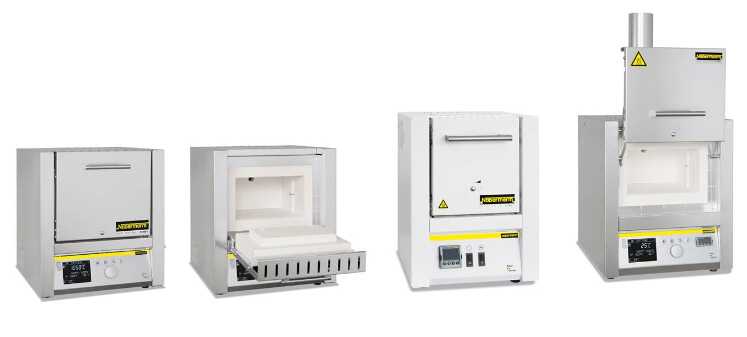
The muffle furnaces L 1/12 - LT 40/12 are the right choice for daily laboratory use. These models stand out for their excellent workmanship,
advanced and attractive design, and high level of reliability. The muffle furnaces come equipped with either a flap door or lift door at no extra charge.
Adjustable air inlet integrated in the door
The muffle furnaces L 1/12 - LT 40/12 are the right choice for daily laboratory use. These models stand out for their excellent workmanship,
advanced and attractive design, and high level of reliability. The muffle furnaces come equipped with either a flap door or lift door at no extra charge.
- Tmax 1100 °C or 1200 °C
- Heating from two sides by ceramic heating plates (heating from three sides for muffle furnaces L 24/11 - LT 40/12)
- Ceramic heating plates with integral heating element which is safeguarded against fumes and splashing, and easy to replace
- Only fiber materials are used which are not classified as carcinogenic according to TRGS 905, class 1 or 2
- Housing made of sheets of textured stainless steel
- Dual shell housing for low external temperatures and high stability Optional flap door (L) which can be used as work platform or lift door (LT) with hot surface facing away from the operator
- Adjustable air inlet integrated in door (see illustration)
- Exhaust air outlet in rear wall of furnace
- Solid state relays provide for low-noise operation
- Defined application within the constraints of the operating instructions
- NTLog Basic for Nabertherm controller: recording of process data with USB-flash drive
Additional equipment
- Chimney, chimney with fan or catalytic converter (not for L 1)
- Over-temperature limiter with adjustable cutout temperature for thermal protection class 2 in accordance with EN 60519-2 as temperature limiter to protect the furnace and load
- Protective gas connection to purge with non-flammable protective or reaction gases (not available in combination with chimney, chimney with fan or catalytic converter)
- Observation hole in the door
- Manual or automatic gas supply system
- Process control and documentation via VCD software package for monitoring, documentation and control
Available Model Number ; Flap door : L 3/11, L 5/11, L 9/11, L 15/11, L 24/11, L 40/11, L 1/12, L 3/12, L 5/12, L 9/12, L 15/12, L 24/12, L 40/12
Lift door : LT 3/11, LT 5/11, LT 9/11, LT 15/11, LT 24/11, LT 40/11, LT 3/12, LT 5/12, LT 9/12, LT 15/12,
LT 24/12, LT 40/12
Muffle Furnaces Basic Models
 |
 |
| Muffle furnace LE 1/11 | Muffle furnace LE 6/11 |
Over-temperature limiter
With their unbeatable price/performance ratio, these compact muffle furnaces are perfect for many applications in the laboratory. Quality
features like the dual shell furnace housing of rust-free stainless steel, their compact, lightweight constructions, or the heating elements encased in quartz glass tubes make these models reliable partners for your application.
- Tmax 1100 °C, working temperature 1050 °C Heating from two sides from heating elements in quartz glass tubes
- Maintenance-friendly replacement of heating elements and insulation
- Only fiber materials are used which are not classified as carcinogenic according to TRGS 905, class 1 or 2
- Housing made of sheets of textured stainless steel
- Dual shell housing for low external temperatures and high stability
- Flap door which can also be used as a work platform
- Exhaust air outlet in rear wall
- Solid state relays provide for low-noise operation
- Compact dimensions and light weight
- Controller mounted under the door to save space
- Defined application within the constraints of the operating instructions
Additional equipment
- Chimney, chimney with fan or catalytic converter (not for L 1)
- Over-temperature limiter with adjustable cutout temperature for thermal protection class 2 in accordance with EN 60519-2 as temperature limiter to protect the furnace and load
- Protective gas connection to purge with non-flammable protective or reaction gases
- Manual gas supply system
- Observation hole in the door
Available Model Number ; LE 1/11, LE 2/11, LE 6/11, LE 14/11
Muffle Furnaces with Brick Insulation and Flap Door or Lift Door
 |
 |
| Muffle furnace LT 5/13 | Muffle furnace L 9/13 |
 Furnace lining with high-quality lightweight refractory brick insulation
Over-temperature limiter
Heating elements on support tubes radiating freely into the
furnace chamber provide for particularly short heating times for these muffle
furnaces. Thanks to their robust lightweight refractory brick insulation, they
can reach a maximum working temperature of 1300 °C. These muffle furnaces thus
represent an interesting alternative to the familiar L(T) 3/11 models,
when you need particularly short heating times or a higher application
temperature.
Furnace lining with high-quality lightweight refractory brick insulation
Over-temperature limiter
Heating elements on support tubes radiating freely into the
furnace chamber provide for particularly short heating times for these muffle
furnaces. Thanks to their robust lightweight refractory brick insulation, they
can reach a maximum working temperature of 1300 °C. These muffle furnaces thus
represent an interesting alternative to the familiar L(T) 3/11 models,
when you need particularly short heating times or a higher application
temperature.
- Tmax 1300 °C
- Heating from two sides
- Heating elements on support tubes ensure free heat radiation and a long service life
- Multi-layer insulation with robust lightweight refractory bricks in the furnace chamber
- Housing made of sheets of textured stainless steel
- Dual shell housing for low external temperatures and stability
- Optional flap door (L) which can be used as work platform or lift door (LT) with hot surface facing away from the operator
- Adjustable air inlet in the furnace door
- Exhaust air outlet in rear wall of furnace
- Solid state relays provide for low-noise operation
- Defined application within the constraints of the operating instructions
- NTLog Basic for Nabertherm controller: recording of process data with USB-flash drive
Additional equipment
- Chimney, chimney with fan or catalytic converter
- Over-temperature limiter with adjustable cutout temperature for thermal protection class 2 in accordance with EN 60519-2 as temperature limiter to protect the furnace and load
- Protective gas connection to purge with non-flammable protective or reaction gases
- Manual or automatic gas supply system
- Observation hole in the door
- Process control and documentation via VCD software package for monitoring, documentation and control
Available Model Number ; L, LT 5/13, L, LT 9/13, L, LT 15/13
Muffle Furnaces up to 1400 °C
 |
 |
|
Muffle furnace L 9/14 |
Muffle furnace L 15/14 |
Over-temperature
limiter
Gas supply
system for non-flammable protective or reactive gas with shutoff valve and flow
meter with regulator valve, optionally with magnetic valve
These models stand out for their excellent workmanship, advanced
and attractive design, and high level of reliability. Heating elements on
support tubes radiating freely into the furnace chamber provide for
particularly short heating times and a maximum temperature of 1400 °C.
These muffle furnaces are a good alternative to the familiar L(T) ../11 series
when higher application temperatures are needed.
- Tmax 1400 °C
- Heating from two sides
- Heating elements on support tubes ensure free heat radiation and a long service life
- Only fiber materials are used which are not classified as carcinogenic according to TRGS 905, class 1 or 2
- Dual shell housing for low external temperatures and high stability
- Adjustable air inlet integrated in door
- Exhaust air outlet in rear wall of furnace
- Solid state relays provide for low-noise operation
- Defined application within the constraints of the operating instructions
- NTLog Basic for Nabertherm controller: recording of process data with USB-flash drive
Additional equipment
- Chimney, chimney with fan or catalytic converter
- Over-temperature limiter with adjustable cutout temperature for thermal protection class 2 in accordance with EN 60519-2 as temperature limiter to protect the furnace and load
- Protective gas connection to purge with non-flammable protective or reaction gases (not available in combination with chimney, chimney with fan or catalytic converter)
- Manual or automatic gas supply system
- Process control and documentation via VCD software package for monitoring, documentation and control
Available Model Number ; L, LT 5/14, L, LT 9/14, L, LT 15/14
Muffle Furnaces with Embedded Heating Elements in the Ceramic Muffle
 |
| L 9/11/SKM |
 Muffle heated
from four sides
Gas supply
system for non-flammable protective or reactive gas with shutoff valve and flow
meter with regulator valve, optionally with magnetic valve
Over-temperature
limiter
We particularly recommend the muffle furnace L 9/11/SKM if your
application involves aggressive substances. The furnace has a ceramic muffle
with embedded heating from four sides. The muffle furnace thus combines a very
good temperature uniformity with excellent protection of the heating elements
from aggressive atmospheres. Another aspect is the smooth, nearly particle free
muffle (furnace door made of fiber insulation), an important quality feature
for some ashing processes.
Muffle heated
from four sides
Gas supply
system for non-flammable protective or reactive gas with shutoff valve and flow
meter with regulator valve, optionally with magnetic valve
Over-temperature
limiter
We particularly recommend the muffle furnace L 9/11/SKM if your
application involves aggressive substances. The furnace has a ceramic muffle
with embedded heating from four sides. The muffle furnace thus combines a very
good temperature uniformity with excellent protection of the heating elements
from aggressive atmospheres. Another aspect is the smooth, nearly particle free
muffle (furnace door made of fiber insulation), an important quality feature
for some ashing processes.
- Tmax 1100 °C
- Muffle heated from four sides
- Furnace chamber with embedded ceramic muffle, high resistance to aggressive gasses and vapours
- Dual shell housing made of sheets of textured stainless steel
- Only fiber materials are used which are not classified as carcinogenic according to TRGS 905, class 1 or 2
- Optional flap door (L) which can be used as work platform or lift door (LT) with hot surface facing away from the operator
- Adjustable working air inlet in the door
- Exhaust air outlet in rear wall of furnace
- Solid state relays provide for lownoise operation
- Defined application within the constraints of the operating instructions
- NTLog Basic for Nabertherm controller: recording of process data with USB-flash drive
Additional equipment
- Chimney, chimney with fan or catalytic converter
- Over-temperature limiter with adjustable cutout temperature for thermal protection class 2 in accordance with EN 60519-2 as temperature limiter to protect the furnace and load
- Protective gas connection to purge with non-flammable protective or reaction gases
- Manual or automation gas supply system
- Observation hole in the door
- Process control and documentation via VCD software package for monitoring, documentation and control
Available Model Number ; L 9/11/SKM, LT 9/11/SKM
Ashing Furnaces with Flap Door or Lift Door
 |
 |
| Ashing furnace LV 3/11 | Ashing furnace LVT 9/11 |
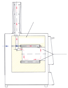 Air inlet
and exhaust flow principle in ashing furnaces
Observation
hole in the door as additional equipment
Over-temperature
limiter
The ashing furnaces LV 3/11 - LVT 15/11 are especially designed
for ashing in the laboratory. A special air intake and exhaust system allows
air exchange of more than 6 times per minute. Incoming air is preheated to
ensure a good temperature uniformity.
Air inlet
and exhaust flow principle in ashing furnaces
Observation
hole in the door as additional equipment
Over-temperature
limiter
The ashing furnaces LV 3/11 - LVT 15/11 are especially designed
for ashing in the laboratory. A special air intake and exhaust system allows
air exchange of more than 6 times per minute. Incoming air is preheated to
ensure a good temperature uniformity.
- Tmax 1100 °C
- Heating from two sides
- Ceramic heating plates with integral heating element which is safeguarded against fumes and splashing, and easy to replace
- Air exchange of more than 6 times per minute
- Good temperature uniformity due to preheating of incoming air
- Only fiber materials are used which are not classified as carcinogenic according to TRGS 905, class 1 or 2
- Housing made of sheets of textured stainless steel
- Dual shell housing for low external temperatures and stability
- Optional flap door (LV) which can be used as work platform or lift door (LVT) with hot surface facing away from the operator
- Solid state relays provide for lownoise operation
- Defined application within the constraints of the operating instructions
- NTLog Basic for Nabertherm controller: recording of process data with USB-flash drive
Additional equipment
- Over-temperature limiter with adjustable cutout temperature for thermal protection class 2 in accordance with EN 60519-2 as temperature limiter to protect the furnace and load
- Observation hole in the door
- Process control and documentation via VCD software package for monitoring, documentation and control
Available Model Number ;
Flap door : LV 3/11, LV 5/11, LV 9/11, LV 15/11,
Lift door: LVT 3/11, LVT 5/11, LVT 9/11, LVT15/11
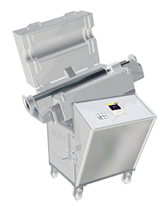
Ashing Furnaces with Integrated Exhaust Gas Cleaning |
 |
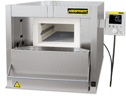
| Ashing furnace L 40/11 BO |
- Tmax 600 °C for the incineration process
- Tmax 1100 °C for the subsequent process
- Three-side heating (both sides and bottom)
- Ceramic heating plates with embedded heating wire
- Only fiber materials are used which are not classified as carcinogenic according to TRGS 905, class 1 or 2
- Dual shell housing made of structured stainless steel provides for low outer temperature and high stability
- Steel collecting pan protects the bottom insulation
- Spring-assisted closing of the furnace door (flap door) with mechanical locking against unintentional opening
- Thermal/catalytic post combustion, integrated in the exhaust channel, up to 600 °C in function
- Temperature control of post combustion can be set up to 850 °C
- Monitored exhaust air
- Inlet-air preheated through the bottom heating plate
- Over-temperature limiter with adjustable cutout temperature for thermal protection class 2 in accordance with EN 60519-2 as temperature limiter to protect the furnace and load
- Defined application within the constraints of the operating instructions
- NTLog Basic for Nabertherm controller: recording of process data with USB-flash drive
Additional equipment
- Process control and documentation via VCD software package for monitoring, documentation and control
 |
| Weighing furnace L 9/11/SW |
 4 scales
available for different maximum weights and scaling areas
Over-temperature
limiter
4 scales
available for different maximum weights and scaling areas
Over-temperature
limiter
 Software
for documentation of the temperature curve and combustion loss using a PC
This weighing furnace with integrated precision scale and
software, was designed especially for combustion loss determination in the
laboratory. The determination of combustion loss is necessary, for instance,
when analyzing sludges and household garbage, and is also used in a variety of
technical processes for the evaluation of results. The difference between the
initial total mass and the combustion residue is the combustion loss. During
the process, the software included records both the temperature and the weight
loss.
Software
for documentation of the temperature curve and combustion loss using a PC
This weighing furnace with integrated precision scale and
software, was designed especially for combustion loss determination in the
laboratory. The determination of combustion loss is necessary, for instance,
when analyzing sludges and household garbage, and is also used in a variety of
technical processes for the evaluation of results. The difference between the
initial total mass and the combustion residue is the combustion loss. During
the process, the software included records both the temperature and the weight
loss.
- Tmax 1100 °C or 1200 °C
- Heating from two sides
- Ceramic heating plates with integral heating element which is safeguarded against fumes and splashing, and easy to replace
- Only fiber materials are used which are not classified as carcinogenic according to TRGS 905, class 1 or 2
- Dual shell housing made of sheets of textured stainless steel
- Optional flap door (L) which can be used as work platform or lift door (LT) with hot surface facing away from the operator
- Adjustable working air inlet in the door
- Exhaust air outlet in rear wall of furnace
- Solid state relays provide for lownoise operation
- Delivery includes base, ceramic plunger with base plate in the furnace lining, precision scale and software package
- 4 scales available for different maximum weights and scaling ranges
- Process control and documentation for temperature and combustion loss via VCD software package for monitoring, documentation and control
- Defined application within the constraints of the operating instructions
Additional equipment
- Chimney, chimney with fan or catalytic converter
- Over-temperature limiter with adjustable cutout temperature for thermal protection class 2 in accordance with EN 60519-2 as temperature limiter to protect the furnace and load
- Observation hole in the door
Available Model Number ;
flap door : L 9/11/SW, L 9/12/SW
Lift door : LT 9/11/SW, LT 9/12/SW
Exhaust Systems/Accessories
* Note: If other controller types are used an adapter cable for connection to mains supply has to be ordered separately. The device will be activated by plugging in the socket.|
|
|
|
||||||
|
Chimney for connection to an exhaust pipe. |
Chimney with fan, to remove exhaust gas from the furnace better. The B400 - P480 controllers can be used to activate the fan automatically (not for models L(T) 15.., L 1/12, LE 1/11, LE 2/11).* |
Catalytic converter with fan for removal of organic components from the exhaust air. Organic components are catalytically oxidized at about 600 °C, broken into carbon dioxide and water vapour. Irritating odors are thus largely eliminated. The B400 - P480 controllers can be used to switch the catalytic converter automatically (not for models L(T) 15.., L 1/12, LE 1/11, LE 2/11).* |
||||||
|
|
|
|
||||||
|
Exhaust torch to burn exhaust gases which are generated during the process. The torch is gas-fired and will be operated with propane gas. If a catalytic post combustion cannot be used for the process this torch is recommended. |
Square saggar for furnaces LHTC and LHT, Tmax 1600 °C The load is placed in ceramic saggars for optimal utilization of the furnace space. Up to three saggars can be stacked on top of each other in the furnace. Each saggar has cut-outs for better ventilation. The top saggar should be closed with a lid made of ceramics also. |
Round saggar (Ø 115 mm) for furnaces LHT/LB, Tmax 1650 °C These saggars are perfectly suited for furnaces LHT/LB. The load is placed in the saggars. Up to three saggars can be stacked on top of each other in order to use the overall furnace chamber. |
||||||


Additional equipment
- Base frame on castors (not for assay furnace N 4/13 CUP)
- Process control and documentation via VCD software package for monitoring, documentation and control
Pit-type furnace with rolling lid
- For bigger charges we offer pit-type furnaces as assay furnaces
Available Model Number : N 4/13 CUP, N 8/13 CUP, N 25/13 CUP
Chamber Furnaces for Annealing, Hardening and Brazing|
|
|
|
Chamber furnace N 7/H as table-top model |
Chamber furnace N 61/H |


Working with protective gas boxes for a protective gas atmosphere using a charging cart
To withstand harsh use in the laboratory, e.g. when heat-treating metals, robust insulation with light refractory bricks is necessary. The chamber furnaces N 7/H - N 87/H are a perfect fit to solve this problem. The furnaces can be extended with a variety of accessories, like annealing boxes for operation under protective gas, roller guides, or a cooling station with a quench tank. Even high-performance applications like the annealing of titanium in medical applications can be implemented without the use of expensive and complicated annealing systems.
- Tmax 1280 °C
- Deep furnace chamber with three-sides heating: from both side walls and bottom
- Heating elements on support tubes ensure free heat radiation and a long service life
- Bottom heating protected by heat-resistant SiC plate
- Low energy consumption due to multi-layer insulation
- Exhaust opening in the side of the furnace, or on back wall of chamber furnace N 31/H and higher
- Base frame included in the delivery, N 7/H - N 17/HR designed as table-top model
- Parallel guided downward swinging door (user protected from heat radiation)
- Gas spring dampers provide for easy door opening and closing
- Defined application within the constraints of the operating instructions
- NTLog Basic for Nabertherm controller: recording of process data with USB-flash drive
 |
 |
| Chamber furnace LH 216/12SW with scale to measure weight reduction during annealing | Chamber furnace LF 60/14 with fresh air fan to accelerate the cooling times |
 Chamber
furnace LH 30/14
Chamber
furnace LH 30/14
 Chamber
furnace LH 30/12 with manual lift door
Chamber
furnace LH 30/12 with manual lift door

LF furnace design provides for shorter heating and cooling times
The chamber furnaces LH 15/12 - LF 120/14 have been trusted for many years as professional chamber furnaces for the laboratory. These furnaces are available with either a robust insulation of light refractory bricks (LH models) or with a combination insulation of refractory bricks in the corners and low heat storage, quickly cooling fiber material (LF models). With a wide variety of optional equipment, these chamber furnaces can be optimally adapted to your processes.- Tmax 1200 °C, 1300 °C, or 1400 °C
- Dual shell housing with rear ventilation, provides for low shell temperatures
- High furnace chamber with five-sided heating for very good temperature uniformity
- Heating elements on support tubes ensure free heat radiation and a long service life
- Controller mounted on furnace door and removable for comfortable operation
- Protection of bottom heating and flat stacking surface provided by embedded SiC plate in the floor
- LH models: multi-layered insulation of light refractory bricks and special backup insulation
- LF models: high-quality fiber insulation with corner bricks for shorter heating and cooling times. Only fiber materials are used which are not classified as carcinogenic according to TRGS 905, class 1 or 2.
- Door with brick-on-brick seal, hand fitted
- Short heating times due to high installed power
- Self-supporting arch for high stability and greatest possible protection against dust
- Quick lock on door
- Motor driven exhaust air flap
- Freely adjustable air inlet integrated in furnace floor
- Base included
- Defined application within the constraints of the operating instructions
- NTLog Basic for Nabertherm controller: recording of process data with USB-flash drive
Additional equipment
- Parallel swinging door, pivots away from operator, for opening when hot
- Lift door with electro-mechanic linear drive
- Separate wall-mounting or floor standing cabinet for switchgear
- Cooling fan for shorter cycle times
- Protective gas connection to purge with non-flammable protective or reaction gases
- Manual or automatic gas supply system
- Scale to measure weight reduction during annealing
- Process control and documentation via VCD software package or Nabertherm Control Center (NCC) for monitoring, documentation and control
Available Model Number : LH 15/12, LH 30/12, LH 60/12, LH 120/12, LH 216/12, LH 15/13, LH 30/13, LH 60/13,
LH 120/13, LH 216/13, LH 15/14, LH 30/14, LH 60/14, LH 120/14, LH 216/14 , LF 15/13, LF 30/13, LF 60/13, LF 120/13, LF 15/14, LF 30/14, LF 60/14, LF 120/14
High-Temperature Furnaces/Sintering Furnaces High-Temperature Furnaces with SiC Rod Heating up to 1600 °C |
 |
| High-temperature furnace LHTC 08/16 | High-temperature furnace LHTCT 01/16 |
 Furnace
chamber with high-quality fiber materials and SiC heating rods on both sides of
the furnace
Furnace
chamber with high-quality fiber materials and SiC heating rods on both sides of
the furnace
 Saggars
with top lid
Saggars
with top lid
- Tmax 1400 °C, 1500 °C, 1550 °C or 1600 °C
- Working temperature 1500 °C (for high-temperature furnaces LHTC ../16), increased wear and tear must be expected in case of working at higher temperatures
- Dual shell housing made of textured stainless steel sheets with additional fan cooling for low surface temperature
- Only fiber materials are used which are not classified as carcinogenic according to TRGS 905, class 1 or 2
- Optional flap door (LHTC) which can be used as work platform or lift door (LHTCT) with hot surface facing away from the operator (High-temperature furnace LHTCT 01/16 only with lift door)
- Switching system with solid-state-relays, power tuned to the SiC rods
- Easy replacement of heating rods
- Adjustable air inlet opening, exhaust air opening in the roof
- Defined application within the constraints of the operating instructions
- NTLog Basic for Nabertherm controller: recording of process data with USB-flash drive
Additional equipment
- Over-temperature limiter with adjustable cutout temperature for thermal protection class 2 in accordance with EN 60519-2 as temperature limiter to protect the furnace and load
- Square saggar for charging of up to three layers
- Lid for top saggar
- Manual or automatic gas supply system
- Process control and documentation via VCD software package for monitoring, documentation and control
 |
 |
| High-temperature furnace LHT 01/17 D | High-temperature furnace LHT 03/17 D |
Saggars
with top lid
- Tmax 1600 °C, 1750 °C, or 1800 °C
- High-quality molybdenum disilicide heating elements
- Dual shell housing made of textured stainless steel sheets with additional fan cooling for low surface temperature
- Only fiber materials are used which are not classified as carcinogenic according to TRGS 905, class 1 or 2
- Compact design with lift door, opening upwards
- Adjustable air inlet
- Exhaust air opening in the roof
- Type B thermocouple
- Defined application within the constraints of the operating instructions
- NTLog Basic for Nabertherm controller: recording of process data with USB-flash drive
Additional equipment
- Over-temperature limiter with adjustable cutout temperature for thermal protection class 2 in accordance with EN 60519-2 as temperature limiter to protect the furnace and load
- Square saggar for charging of up to three layers
- Protective gas connection to purge with non-flammable protective or reaction gases
- Manual or automatic gas supply system
- Process control and documentation via VCD software package for monitoring, documentation and control
Available Model Number : LHT 02/16, LHT 04/16, LHT 08/16, LHT 01/17 D, LHT 03/17 D, LHT 02/17, LHT 04/17,
LHT 08/17, LHT 02/18, LHT 04/18, LHT 08/18
High-Temperature Bottom Loading Furnaces up to 1700 °C
, |
 |
| LHT 16/17 LB | High-temperature furnace LHT 02/17 LB with a set of saggars |
 Electrically
driven lift-bottom
Electrically
driven lift-bottom
 Saggar
The motor-driven lifting table significantly simplifies the
charging of the high-temperature furnaces LHT/LB. The heating all around the
cylindrical furnace chamber provides for an opitimal temperature uniformity.
For the tabletop models LHT 01/17 LB and LHT 02/17 LB the charge can be placed
in charge saggars made of technical ceramics. Up to three charge saggars can be
stacked on top of each other resulting in a high productivity. Due to its
volume the high-temperature furnace LHT 16/17 LB can also be used for
applications in production.
Saggar
The motor-driven lifting table significantly simplifies the
charging of the high-temperature furnaces LHT/LB. The heating all around the
cylindrical furnace chamber provides for an opitimal temperature uniformity.
For the tabletop models LHT 01/17 LB and LHT 02/17 LB the charge can be placed
in charge saggars made of technical ceramics. Up to three charge saggars can be
stacked on top of each other resulting in a high productivity. Due to its
volume the high-temperature furnace LHT 16/17 LB can also be used for
applications in production.
- Tmax 1650 °C, 1700 °C (LHT 16/17 LB)
- High-quality heating elements made of molybdenum disilicide offer best possible protection against chemical interaction between charge and heating elements
- Only fiber materials are used which are not classified as carcinogenic according to TRGS 905, class 1 or 2
- Outstanding temperature uniformity due to all-round furnace chamber heating
- Furnace chamber with a volume of 1, 2 or 16 liters, table with large floor space
- Precise, motorized toothed belt drive of the table with button operation
- Appealing, dual shell stainless steel housing
- Exhaust air vent in the roof
- Type S thermocouple
- Defined application within the constraints of the operating instructions
- NTLog Basic for Nabertherm controller: recording of process data with USB-flash drive
Additional equipment
- Over-temperature limiter with adjustable cutout temperature for thermal protection class 2 in accordance with EN 60519-2 as temperature limiter to protect the furnace and load
- Stackable saggars for loading in up to two or three levels, depending on model
- Protective gas connection to purge with non-flammable protective or reaction gases
- Manual or automatic gas supply system
- Adjustable air inlet through the floor
- Process control and documentation via VCD software package for monitoring, documentation and control
|
|
|
High-temperature furnace LHT 04/16 SW with scale for measuring weight reduction during annealing and with gas supply system |


Software for documentation of the temperature curve and combustion loss using a PC
These high-temperature furnaces were specially developed to determine combustion loss during annealing and for thermogravimetric analysis (TGA) in the lab. The complete system consists of the high-temperature furnace for 1600 °C or 1750 °C, a table frame, precision scale with feedthroughs into the furnace and powerful software for recording both the temperature curve and the weight loss over time.
- Defined application within the constraints of the operating instructions
- Technical description of the furnaces: see models LHT 04/16 and LHT 04/17
- Description of the weighing system: see models L 9/... SW
- Process control and documentation for temperature and combustion loss via VCD software package for monitoring, documentation and control
|
|
|
|
High-temperature furnace HT 16/18 with gas supply system |
High-temperature furnace HT 160/17 with gas supply system |


Reinforced floor as protection for bottom insulation for high-temperature furnace HT 16/16 and higher

Inner process top hat with gas injection through the furnace bottom protects the furnace chamber against contamination and/or prevents chemical interaction between the charge and heating elements

High-temperature furnace HT 64/16S with pneumatically driven and parallel lift door

Two-door design for high-temperature furnaces > HT 276/..
Available Model Number : HT 04/16, HT 08/16, HT 16/16, HT 40/16, HT 64/16, HT 128/16, HT 160/16, HT 276/16,
HT 450/16, HT 04/17, HT 08/17, HT 16/17, HT 40/17, HT 64/17, HT 128/17, HT 160/17, HT 276/17, HT 450/17, HT 04/18,
HT 08/18, HT 16/18, HT 40/18, HT 64/18, HT 128/18, HT 160/18, HT 276/18, HT 450/18,
High-Temperature Furnaces with SiC Rod Heating up to 1550 °C
|
|
|
High-temperature furnace HTC 40/16 |


Vertically mounted SiC rods and optional perforated air inlet tubes of the debinding system in a high-temperature furnace

Exhaust air flap and charge thermocouple including a stand as additional equipment
The high-temperature furnaces HTC 16/16 - HTC 450/16 are heated by vertically hung SiC rods, which makes them especially suitable for sintering processes up to a maximum operating temperature of 1550 °C. For some processes, e.g. for sintering zirconium oxide, the absence of interactivity between the charge and the SiC rods, these models are more suitable than the alternatives heated with molybdenum disilicide elements. The basic construction of these furnaces make them comparable with the already familiar models in the HT product line and they can be upgraded with the same additional equipment.
- Tmax 1550 °C
- Dual shell housing with fan cooling for low shell temperatures
- Heating from both sides via vertically mounted SiC rods
- High-quality fiber insulation backed by special insulation
- Side insulation constructed with tongue and groove blocks provides for low heat loss to the outside
- Long-life roof insulation with special suspension
- Only fiber materials are used which are not classified as carcinogenic according to TRGS 905, class 1 or 2
- Chain-guided parallel swivel door for defined opening and closing of the door without destroying the insulation
- Two-door design (front/back) for high-temperature furnaces > HTC 276/..
- Labyrinth sealing ensures the least possible temperature loss in the door area
- Reinforced floor as protection for bottom insulation
- Exhaust air opening in the furnace roof
- Heating elements switched via SCR's
- Over-temperature limiter with adjustable cutout temperature for thermal protection class 2 in accordance with EN 60519-2 as temperature limiter to protect the furnace and load
- Defined application within the constraints of the operating instructions
- NTLog Basic for Nabertherm controller: recording of process data with USB-flash drive
Available Model Number : HTC 16/16, HTC 40/16, HTC 64/16, HTC 128/16, HTC 160/16, HTC 276/16, HTC 450/16
High Temperature Furnaces with Molybdenum Disilicide Heating Elements with Refractory Brick Insulation up to 1700 °C
 |
 |
| High-temperature furnace HFL 16/17 DB50 | High-temperature furnace HFL 160/17 |
 Protection
grid in front of heating elements prevent against mechanical damages
Protection
grid in front of heating elements prevent against mechanical damages
 Gas supply
system for non-flammable protective or reaction gases
The high-temperature furnaces HFL 16/16 HFL 160/17 are
characterized by their lining with robust light refractory bricks. This version
is recommended for processes producing aggressive gases or acids, such as under
glass melting.
Gas supply
system for non-flammable protective or reaction gases
The high-temperature furnaces HFL 16/16 HFL 160/17 are
characterized by their lining with robust light refractory bricks. This version
is recommended for processes producing aggressive gases or acids, such as under
glass melting.
Standard equipment like high-temperature furnaces HT, except:
- Tmax 1600 °C or 1700 °C
- Robust refractory brick insulation and special backing insulation
- Furnace floor made of lightweight refractory bricks accommodates high charge weights
- Defined application within the constraints of the operating instructions
- NTLog Basic for Nabertherm controller: recording of process data with USB-flash drive
Available Model Number : HFL 16/16, HFL 40/16, HFL 64/16, HFL 160/16, HFL 16/17, HFL 40/17, HFL 64/17,
HFL 160/17
Ovens and Forced Convection Chamber Furnaces |
 |
| Oven TR 60 with adjustable fan speed | Oven TR 240 |
 Electrical
rotating device as additional equipment
Electrical
rotating device as additional equipment
 Extricable
metal grids to load the oven in different layers
Extricable
metal grids to load the oven in different layers
 Oven TR
1050 with double door
Oven TR
1050 with double door
 Oven
TR 120 LS with safety technology according to EN 1539 for charges
containing liquid solvents
Oven
TR 120 LS with safety technology according to EN 1539 for charges
containing liquid solvents
 Oven TR
450
With their maximum working temperature of up to 300 °C and air
circulation, the ovens achieve a perfect temperature uniformity which is much
better than in ovens of most competitors. They can be used for various
applications such as e.g. drying, sterilizing or warm storing. Ample
warehousing of standard models provides for short delivery times.
Oven TR
450
With their maximum working temperature of up to 300 °C and air
circulation, the ovens achieve a perfect temperature uniformity which is much
better than in ovens of most competitors. They can be used for various
applications such as e.g. drying, sterilizing or warm storing. Ample
warehousing of standard models provides for short delivery times.
- Tmax 300 °C
- Working temperature range: + 5 °C above room temperature up to 300 °C
- Ovens TR 30 - TR 240 designed as tabletop models
- Ovens TR 450 and TR 1050 designed as floor standing models
- Horizontal, air circulation results in temperature uniformity better than +/- 5 °C
- Stainless steel chamber, alloy 304 (AISI)/(DIN material no. 1.4301), rust-resistant and easy to clean
- Only fiber materials are used which are not classified as carcinogenic according to TRGS 905, class 1 or 2
- Large handle to open and close the door
- Charging in multiple layers possible using removeable grids (number of removeable grids included, see table to the right)
- Large, wide-opening swing door, hinged on the right with quick release for models TR 30 - TR 450
- Double swing door with quick release for TR 1050
- TR 1050 equipped transport rollers
- Infinitely adjustable exhaust at the rear wall with operation from the front
- PID microprocessor control with self-diagnosis system
- Solid state relays provide for lownoise operation
- Defined application within the constraints of the operating instructions
- NTLog Basic for Nabertherm controller: recording of process data with USB-flash drive
Additional equipment
- Over-temperature limiter with adjustable cutout temperature for thermal protection class 2 in accordance with EN 60519-2 as temperature limiter to protect the oven and load
- Infinitely adjustable fan speed of the air circulation fan
- Window for charge observing
- Further removeable grids with rails
- Side inlet
- Stainless steel collecting pan to protect the furnace chamber
- Door hinges on the left side
- Reinforced bottom plate
- Safety technology according to EN 1539 for charges containing liquid solvents (TR .. LS) up to model TR 240 LS, achievable temperature uniformity +/- 8 °C
- Transport castors for model TR 450
- Various modifications available for individual needs
- Upgrading available to meet the quality requirements of AMS 2750 E or FDA
- Process control and documentation via VCD software package for monitoring, documentation and control
 |
 |
| Chamber oven KTR 1500 with charging cart | Chamber oven KTR 22500/S with chamber lightning and drive-in tracks with insulated plugs which provide for an optimal temperature uniformity |
 KTR 3100/S
for curing of composites in vacuum bags incl. pump and necessary connections in
the oven chamber
KTR 3100/S
for curing of composites in vacuum bags incl. pump and necessary connections in
the oven chamber
 Direct
gas-firing at a chamber dryer
Direct
gas-firing at a chamber dryer
 KTR 4500
with platform cart, inner lightning and observation windows
KTR 4500
with platform cart, inner lightning and observation windows
 Adjustable
plate shutters to adapt the air guide to the charge
Adjustable
plate shutters to adapt the air guide to the charge
 KTR 3100
DT with rotating system for tempering of silicone parts. Four baskets will be
charged in the frame and can be taken out separately
KTR 3100
DT with rotating system for tempering of silicone parts. Four baskets will be
charged in the frame and can be taken out separately
 Drive-in
ramp
The chamber ovens of the KTR range can be used for complex
drying processes and heat treatment of charges to an application temperature of
260 °C. The high-performance air circulation enables optimum temperature
uniformity throughout the work space. A wide range of accessories allow the
chamber ovens to be modified to meet specific process requirements. The design
for the heat treatment of flammable materials in conformance with EN 1539
(NFPA 86) is available for all sizes.
Drive-in
ramp
The chamber ovens of the KTR range can be used for complex
drying processes and heat treatment of charges to an application temperature of
260 °C. The high-performance air circulation enables optimum temperature
uniformity throughout the work space. A wide range of accessories allow the
chamber ovens to be modified to meet specific process requirements. The design
for the heat treatment of flammable materials in conformance with EN 1539
(NFPA 86) is available for all sizes.
- Tmax 260 °C
- Electrically heated (via a heating register with integrated chrome steel heating elements) or gas-fired (direct or indirect gas-fired including injection of the hot air into the intake duct)
- Temperature uniformity up to +/- 3 °C according to DIN 17052-1 (for design wihout track cutouts)
- High-quality mineral wool insulation provides for outer temperatures of < 25 °C above room temperature
- Only fiber materials are used which are not classified as carcinogenic according to TRGS 905, class 1 or 2
- High air exchange for fast drying processes
- Double-wing door for furnaces KTR 3100 and larger
- Over-temperature limiter with adjustable cutout temperature for thermal protection class 2 in accordance with EN 60519-2 as temperature limiter to protect the oven and load
- Incl. floor insulation
- Defined application within the constraints of the operating instructions
- NTLog Basic for Nabertherm controller: recording of process data with USB-flash drive
Additional equipment
- Track cutouts for level drive-in of charging cart
- Base frame to charge the oven via a charging forklift
- Additional Door in the back for charging from both sides or to use the oven as lock between two rooms
- Fan system for faster cooling with manual or motor-driven control of the exhaust flaps
- Programmed opening and closing of exhaust air flaps
- Air circulation with speed control, recommendable for processes with light or sensitive charge
- Observation window and furnace chamber lighting
- Safety technology according to EN 1539 (NFPA 86) (models KTR .. LS) for charges containing solvents
- Charging cart with or without rack system
- Design for clean room heat treatment processes
- Rotating systems for tempering processes
- Process control and documentation via VCD software package or Nabertherm Control Center (NCC) for monitoring, documentation and control
Accessories
- Adjustable plate shutters to adapt the air guide to the charge and improve temperature uniformity
- Guide-in tracks and shelves
- Shelves with 2/3 extraction with evenly distributed load on the whole shelve surface
- Platform cart in combination with drive-in tracks
- Charging cart with rack system in combination with drive-in tracks
- Sealing shoes for ovens with drive-in tracks to improve temperature uniformity in the work space
- All KTR-models are also available with Tmax 300 °C.
|
|
|
|
Forced convection chamber furnace NA 250/45 |
Forced convection chamber furnace NA 120/46 with lift door |


Forced convection chamber furnace NA 15/65 as table-top model
These chamber furnaces with air circulation are characterized by their extremely high temperature uniformity. Hence, they are especially suitable for processes such as cooling, crystalizing, preheating, curing, but also for numerous processes in tool making. Due to the modular concept, the forced convection furnaces can be adjusted to the process requirements by adding suitable equipment.
- Tmax 450 °C, 650 °C, or 850 °C
- Horizontal air circulation
- Swing door hinged on the right
- Temperature uniformity up to +/- 4 °C according to DIN 17052-1 (model NA 15/65 up to +/- 5 °C)
- Optimum air flow and temperature uniformity through high circulation rates
- One frame sheet and rails for two additional trays included in the scope of delivery (NA 15/65 without frame sheet)
- Stainless steel air-baffles in the furnace for optimum air circulation
- Base frame included in the delivery, NA 15/65 designed as table-top model
- Air inlet and exhaust air flaps as additional equipment for using as drying oven
- Defined application within the constraints of the operating instructions
- NTLog Basic for Nabertherm controller: recording of process data with USB-flash drive
Available Model Number : NA 30/45, NA 60/45, NA 120/45, NA 250/45, NA 500/45, NA 15/65, NA 30/65, NA 60/65, NA 120/65, , NA 250/65, NA 500/65, N 30/85 HA, N 60/85 HA, N 120/85 HA, N 250/85 HA, N 500/85 HA
Sealed Forced Convection Chamber Furnaces NA-I and NA-SI
 |
 |
| Forced convection chamber furnace NA 120/65 I | Forced convection chamber furnace NA 15/65 I as tabletop model with manual gas supply system |
NA-I design Like forced convection chamber furnaces < 675 l (page 34) with the following changes
- Tmax 450 °C and 650 °C
- Silicone door seal
- Furnace housing sealed with silicone
- Protective gas connection in the back wall
- Defined application within the constraints of the operating instructions
- Residual oxygen concentration < 1 % depending on the volume and type of protective gas
- For non-flammable protective and reaction gases such as argon, nitrogen, and forming gas (national regulations must be considered)
NA-SI design Additional features
- Tmax 650 °C
- Welded inner housing
- 2-sided heating and air circulation
- Door sealed with seal gas
- Sealed connection to circulation motor
- Gas inlet via circulator shaft
- Defined application within the constraints of the operating instructions
- Residual oxygen concentration to 0.1 % depending on the volume and type of protective gas
- For non-flammable protective and reaction gases such as argon, nitrogen, and forming gas (national regulations must be considered)
Available Model Number : NA 30/45 I, NA 60/45 I, NA 120/45 I, NA 250/45 I, NA 500/45 I, NA 675/45 I, NA 15/65 I1, NA 30/65 I, N A 60/65 I (SI), NA 120/65 I (SI), NA 250/65 I (SI), NA 500/65 I (SI), NA 675/65 I
Chamber Furnaces for Processes with High Vaporization Rates of Organic Matter or for Thermal Cleaning by Ashing Electrically Heated or Gas-Fired

 Chamber
furnace N 650/14 BO with ignition burner
The chamber furnaces of the model series N(B) .. BO
are used for processes with large amounts of organic matters or high
vaporization rates. These models can be used for products which are insensitive
against temporarily uncontrolled temperature increases. Processes in which the
product or contaminations on the product are ashed by ignition can be also
carried out safely in this type of chamber furnace. Examples include residual
wax removal of pouring clustersfollowed by sintering, or thermal cleaning of
oxide catalytic honey combs from soot or fuel residues. The electrically heated
N...BO furnaces can be used for processes with exact temperature control and
uniformity. For safety reasons, they are equipped with an integrated gas torch
for igniting the flammable components in the gas mixture. The accumulation of
flammable components is avoided and their safe combustion is ensured.
The gas-fired NB…BO furnaces are designed for processes which
require a heat-up time to temperatures > 500 °C
The burning of unwanted organic ingrediants can take place at
temperatures > 500 °C. Following this, a subsequent process can take place
up to max. 1400 °C (electrically) or up to 1000 °C (gas-fired).
For safety, the furnace door locks after the program was started
and cannot be opened again until the temperature has dropped below a defined
value. In case of burner malfunction or gas shortage the process is aborted.
Chamber
furnace N 650/14 BO with ignition burner
The chamber furnaces of the model series N(B) .. BO
are used for processes with large amounts of organic matters or high
vaporization rates. These models can be used for products which are insensitive
against temporarily uncontrolled temperature increases. Processes in which the
product or contaminations on the product are ashed by ignition can be also
carried out safely in this type of chamber furnace. Examples include residual
wax removal of pouring clustersfollowed by sintering, or thermal cleaning of
oxide catalytic honey combs from soot or fuel residues. The electrically heated
N...BO furnaces can be used for processes with exact temperature control and
uniformity. For safety reasons, they are equipped with an integrated gas torch
for igniting the flammable components in the gas mixture. The accumulation of
flammable components is avoided and their safe combustion is ensured.
The gas-fired NB…BO furnaces are designed for processes which
require a heat-up time to temperatures > 500 °C
The burning of unwanted organic ingrediants can take place at
temperatures > 500 °C. Following this, a subsequent process can take place
up to max. 1400 °C (electrically) or up to 1000 °C (gas-fired).
For safety, the furnace door locks after the program was started
and cannot be opened again until the temperature has dropped below a defined
value. In case of burner malfunction or gas shortage the process is aborted.
Chamber furnaces N 100 BO - N 650/14 BO, electrically heated and gas-fired ignition flame
- Tmax 1000 °C or 1400 °C
- Only fiber materials are used which are not classified as carcinogenic according to TRGS 905, class 1 or 2
- Standard sizes up to 650 liters furnace chamber, additional sizes on request
- Exhaust hood
- Fully automatic temperature control
- Optional thermal afterburning
- Ignition flame using natural gas or liquid gas (LPG)
- Defined application within the constraints of the operating instructions
Chamber furnaces models NB 300 BO and NB 650 BO, gas-fired
- Tmax 1000 °C
- Only fiber materials are used which are not classified as carcinogenic according to TRGS 905, class 1 or 2
- Standard sizes up to 650 liters furnace chamber, additional sizes on request
- Integrated thermal afterburning
- Gas burners operating with natural gas or liquid gas (LPG)
- Defined application within the constraints of the operating instructions
|
|
|
|
KTR 8000 designed as a production oven in the clean room with filters for air circulation |
Hot-wall retort furnace NRA 1700/06 with charging frame for installation in grey room with charging door in clean room |


High-temperature furnace with loading from the clean room; switchgear and furnace installed in grey room

Forced convection chamber oven NAC 250/45 with clean room specs
Clean room applications impose particularly high requirements to the design of the chosen furnace. If the complete furnace is operated in a clean room an essential contamination of the clean room atmosphere must be avoided. Especially, the particle contamination must be reduced to a minimum.
The specific application determines the choice of the required furnace technology. In many cases forced convection furnaces are required to achieve the necessary temperature uniformity at lower temperatures. For higher temperatures, Nabertherm has also delivered many furnaces with radiant heating.
Furnace Installation in the Clean Room
If the complete furnace is supposed to be positioned in the clean room, then it is important that both the furnace chamber and the furnace housing as well as the controls provide for good protection against contamination. Surfaces must be easy to clean. The furnace chamber is tightly sealed to the insulation behind it. If necessary, additional equipment such as filters for the fresh air supply or the air circulation in the furnace can be used to improve the cleanliness class. It is recommended to install the switchgear and the furnace controls outside the clean room.
Furnace Installation in the Grey Room, Furnace Charging from the Clean Room
Optimal results with respect to cleanness will be achieved by placing the furnace in the grey room with charging from the clean room. This significantly reduces the amount of costly space needed in the clean room to a minimum. The front and the furnace interior in the clean room are designed for easy cleaning. With this configuration even the highest clean room classes can be achieved.
Sluice Furnace between Grey Room and Clean Room
Logistics between clean room and grey room can often be easily sorted out. Lock furnaces with one door in the grey room and the other door in the clean room are the perfect choice for these applications. The inner chamber as well as the furnace front in the clean room will be especially designed for lowest particle contamination.
Please contact us if you are looking for a heat treatment solution under clean room conditions. We would be pleased to quote for the oven or furnace model that meets best your requirements.
Tube Furnaces and Accessories |
| RD 30/200/11 |
- Tmax 1100 °C or 1300 °C
- Dual shell housing made of sheets of textured stainless steel
- Only fiber materials are used which are not classified as carcinogenic according to TRGS 905, class 1 or 2
- Inner diameter of the tube: 30 mm, heated length: 200 mm
- Working tube made of C 530 material including two fiber plugs as standard
- Thermocouple type K (1100 °C) or type S (1300 °C)
- Solid state relays provide for low-noise operation of the heating
- Heating wires wound directly around the working tube resulting in very fast heat-up rates
- Defined application within the constraints of the operating instructions
Additional equipment
- Over-temperature limiter with adjustable cutout temperature for thermal protection class 2 in accordance with EN 60519-2 as temperature limiter to protect the furnace and load
- Gas supply system for non-flammable protective or reactive gas
 |
 |
| Tube furnace R 170/1000/13 | Tube furnace R 50/250/13 with gas supply system 2 |
- Tmax 1200 °C or 1300 °C
- Single-zoned design as standard
- Dual shell housing made of sheets of textured stainless steel
- Only fiber materials are used which are not classified as carcinogenic according to TRGS 905, class 1 or 2
- Outer tube diameter of 50 mm to 170 mm, heated length from 250 mm to 1000 mm
- Working tube of C 530 ceramic including two fiber plugs as standard equipment
- Tmax 1200 °C: Type N thermocouple
- Tmax 1300 °C: Type S thermocouple
- Solid state relays provide for lownoise operation
- Defined application within the constraints of the operating instructions
- NTLog Basic for Nabertherm controller: recording of process data with USB-flash drive
Additional equipment
- Over-temperature limiter with adjustable cutout temperature for thermal protection class 2 in accordance with EN 60519-2 as temperature limiter to protect the furnace and load
- Charge control with temperature measurement in the working tube and in the furnace chamber outside the tube
- Three-zoned design (heated length from 500 mm)
- Gas supply systems for protective gas or vacuum operation
- Process control and documentation via VCD software package for monitoring, documentation and control
|
|
|
|
Tube furnace RT 50-250/11 |
Tube furnace RT 50-250/13 |


These compact tube furnaces are used when laboratory experiments must be performed horizontally, vertically, or at specific angles. The ability to configure the angle of tilt and the working height, and their compact design, also make these tube furnaces suitable for integration into existing process systems.
- Tmax 1100 °C, 1300 °C, or 1500 °C
- Compact design
- Only fiber materials are used which are not classified as carcinogenic according to TRGS 905, class 1 or 2
- Vertical or horizontal operation freely adjustable
- Working height freely adjustable
- Working tube made of C 530 ceramic
- Type S thermocouple
- Operation also possible separate from stand if safety guidelines are observed
- Control system integrated in furnace base
- Defined application within the constraints of the operating instructions
- NTLog Basic for Nabertherm controller: recording of process data with USB-flash drive
 |
 |
| Tube furnace RHTC 80-230/15 with manual gas supply system | Tube furnace RHTC 80-450/15 |
 SiC rod
heating
These compact tube furnaces with SiC rod heating and integrated
switchgear and controller can be used universally for many processes. With an
easy to replace working tube as well as additional standard equipment options,
these furnaces are flexible and can be used for a wide range of applications.
The high-quality fiber insulation ensures fast heating and cooling times. The
SiC heating rods installed parallel to the working tube ensure excellent
temperature uniformity. The price-performance ratio for this temperature range
is unbeatable.
SiC rod
heating
These compact tube furnaces with SiC rod heating and integrated
switchgear and controller can be used universally for many processes. With an
easy to replace working tube as well as additional standard equipment options,
these furnaces are flexible and can be used for a wide range of applications.
The high-quality fiber insulation ensures fast heating and cooling times. The
SiC heating rods installed parallel to the working tube ensure excellent
temperature uniformity. The price-performance ratio for this temperature range
is unbeatable.
- Tmax 1500 °C
- Dual shell housing made of sheets of textured stainless steel
- Only fiber materials are used which are not classified as carcinogenic according to TRGS 905, class 1 or 2
- Active cooling of housing for low surface temperatures
- Type S thermocouple
- Solid state relays provide for low-noise operation
- Prepared for assembly of working tubes with water-cooled flanges
- Ceramic tube, C 799 quality
- Defined application within the constraints of the operating instructions
- NTLog Basic for Nabertherm controller: recording of process data with USB-flash drive
Additional equipment
- Over-temperature limiter with adjustable cutout temperature for thermal protection class 2 in accordance with EN 60519-2 as temperature limiter to protect the furnace and load
- Charge control with temperature measurement in the working tube and in the furnace chamber outside the tube
- Fiber plugs
- Check valve at gas outlet avoids intrusion of false air
- Working tubes for operation with water-cooled flanges
- Display of inner tube temperature with additional thermocouple
- Alternative gas supply systems for protective gas or vacuum operation
- Process control and documentation via VCD software package for monitoring, documentation and control
 |
 |
| Tube furnace RHTH 120/600/17 | Tube furnace RHTV 120/480/16 LBS with working tube closed at one side, protective gas and vacuum option as well as with electric screw drive of the lift table |
 RHTV
50/150/17 vertical tube furnace with stand and gas supply system 2 as additional
equipment
RHTV
50/150/17 vertical tube furnace with stand and gas supply system 2 as additional
equipment
 Tube
furnace RHTH 120/600/18
The high-temperature tube furnaces are available in either
horizontal (type RHTH) or vertical (type RHTV) designs. High-quality insulation
materials made of vacuum-formed fiber plates enable energy-saving operation and
a fast heating time due to low heat storage and heat conductivity. By using
different gas supply systems, operations can be performed under non-flammable
or flammable protective or reactive gases or under vacuum.
Tube
furnace RHTH 120/600/18
The high-temperature tube furnaces are available in either
horizontal (type RHTH) or vertical (type RHTV) designs. High-quality insulation
materials made of vacuum-formed fiber plates enable energy-saving operation and
a fast heating time due to low heat storage and heat conductivity. By using
different gas supply systems, operations can be performed under non-flammable
or flammable protective or reactive gases or under vacuum.
- Tmax 1600 °C, 1700 °C, or 1800 °C
- MoSi2 heating elements, mounted vertically for easy replacement
- Insulation with vacuum-formed ceramic fiber plates
- Only fiber materials are used which are not classified as carcinogenic according to TRGS 905, class 1 or 2
- Rectangular outer housing with slots for convection cooling
- Tube furnaces RHTV with frame for vertical operation
- Dual shell housing made of sheets of textured stainless steel
- Ceramic working tube made of material C 799 incl. fiber plugs for operation under air
- Type B thermocouple
- Power unit with low-voltage transformer and thyristor
- Over-temperature limiter with adjustable cutout temperature for thermal protection class 2 in accordance with EN 60519-2 as temperature limiter to protect the furnace and load and with selectable maximum temperature gradient as tube protection
- Switchgear and control unit separate from furnace in separate floor standing cabinet
- Defined application within the constraints of the operating instructions
- NTLog Basic for Nabertherm controller: recording of process data with USB-flash drive
Additional equipment
- Charge control with temperature measurement in the working tube and in the furnace chamber outside the tube
- Display of inner tube temperature with additional thermocouple
- Gas tight flanges for protective gas and vacuum operation
- Manual or automatic gas supply system
- Three-zone control for optimization of temperature uniformity (only tube furnaces RHTH)
- Check valve at gas outlet avoids intrusion of false air
- Process control and documentation via VCD software package or Nabertherm Control Center (NCC) for monitoring, documentation and control
 |
 |
| Tube furnace RSV 170/1000/11 with gas supply system 2 | Tube furnace RSH 80/500/13 with gas tight tube and water-cooled flanges |
 Tube
furnace RS 120/750/13 with gas supply system 4, hydrogen applications
Tube
furnace RS 120/750/13 with gas supply system 4, hydrogen applications
 Quartz
glass and flanges for protective gas operation as optional equipment
Quartz
glass and flanges for protective gas operation as optional equipment
 Tube
furnace RSH 120/1000/11S, three-zone controlled, incl. zone separators to reach
a temperature gradient
Tube
furnace RSH 120/1000/11S, three-zone controlled, incl. zone separators to reach
a temperature gradient
 Tube furnace
RSH 50/500/13
These tube furnaces can be used for horizontal (RSH) or vertical
(RSV) operation. The split-type design makes it easy to change the working
tube. It allows for a comfortable exchange of various working tubes (e.g.
working tubes made of different materials).
Using the wide range of accessories these professional tube
furnaces can be optimally tailored to your process. By upgrading the furnaces
with different gas supply systems the operation in a protective gas atmosphere,
under vacuum or under flammable protective or reactive gases is possible.
Besides convenient standard controllers for process control modern PLC control
systems are also available.
Tube furnace
RSH 50/500/13
These tube furnaces can be used for horizontal (RSH) or vertical
(RSV) operation. The split-type design makes it easy to change the working
tube. It allows for a comfortable exchange of various working tubes (e.g.
working tubes made of different materials).
Using the wide range of accessories these professional tube
furnaces can be optimally tailored to your process. By upgrading the furnaces
with different gas supply systems the operation in a protective gas atmosphere,
under vacuum or under flammable protective or reactive gases is possible.
Besides convenient standard controllers for process control modern PLC control
systems are also available.
- Tmax 1100 °C or 1300 °C
- Dual shell housing made of sheets of textured stainless steel
- Only fiber materials are used which are not classified as carcinogenic according to TRGS 905, class 1 or 2
- Tmax 1100 °C: Type N thermocouple
- Tmax 1300 °C: Type S thermocouple
- Frame for vertical operation (RSV)
- Split-type design for simple insertion of the working tube
- Working tube made of material C 530 incl. fiber plugs for operation under air in scope of delivery
- Heating elements on support tubes provide for free radiation
- RSV: switchgear and control unit separate from furnace in own wall or standing cabinet
- RSH: switchgear and control unit integrated in furnace housing
- Defined application within the constraints of the operating instructions
- NTLog Basic for Nabertherm controller: recording of process data with USB-flash drive
Additional equipment
- Charge control with temperature measurement in the working tube and in the furnace chamber outside the tube
- Display of inner tube temperature with additional thermocouple
- Different gas supply systems for non-flammable or flammable protective or reactive gases and vacuum operation
- Three-zone control for optimization of temperature uniformity
- Cooling systems for accelerated cooling of the working tube and charge
- Check valve at gas outlet avoids intrusion of false air
- Base frame with integrated switchgear and controller
- Process control and documentation via VCD software package or Nabertherm Control Center (NCC) for monitoring, documentation and control
Available Model Number ; RSH 50/250/.., RSH 50/500/.., RSH 80/500/.., RSH 80/750/.., RSH 120/500/.,
RSH 120/750/., RSH 120/1000/, RSH 170/750/, RSH 170/1000/, RSV 50/250/.., RSV 50/500/., RSV 80/500/.., RSV 80/750/., RSV 120/500/, RSV 120/750/., RSV 120/1000/., RSV 170/750/.., RSV 170/1000/.
Rotary Tube Furnaces for Batch Operation up to 1100 °C
  |
|
| Rotary tube furnace RSRB 80/500/11 as tabletop version for batch operation | Rotary tube furnace RSRB 120/500/11 |
 Rotary
tube furnace tilted towards the right side for charging and batch operation
Rotary
tube furnace tilted towards the right side for charging and batch operation
 Rotary
tube furnace tilted towards the left side to discharge
Rotary
tube furnace tilted towards the left side to discharge
 Connection
set for vacuum operation
Connection
set for vacuum operation
 Gas tight
closing plug for tubes made of quartz glass closed at one side
The rotary tube furnaces of the RSRB series are ideally suited
for batch operation. The permanent rotation of the working tube ensures that
the charge is constantly in motion. Due to the special shape of the quartz
reactor with the tapered pipe ends the batch is kept in the rotary tube furnace
and can be heat-treated an arbitrarily long time period time; a controlled
heating to the temperature profiles is also possible.
Gas tight
closing plug for tubes made of quartz glass closed at one side
The rotary tube furnaces of the RSRB series are ideally suited
for batch operation. The permanent rotation of the working tube ensures that
the charge is constantly in motion. Due to the special shape of the quartz
reactor with the tapered pipe ends the batch is kept in the rotary tube furnace
and can be heat-treated an arbitrarily long time period time; a controlled
heating to the temperature profiles is also possible.
- Tmax 1100 °C
- Thermocouple type K
- Dual shell housing made of sheets of textured stainless steel
- Only fiber materials are used which are not classified as carcinogenic according to TRGS 905, class 1 or 2
- Tube furnace designed as table-top model with quartz glass reactor which opens on both sides, tapered ends
- Reactor is removed for emptying out of the rotary tube furnace. Beltless drive and hinged furnace housing (opening temperature < 180 °C) provide for very easy removal through
- Adjustable drive of approx. 2-45 rpm
- Switchgear and control unit separate from tube furnace in own wall or standing cabinet
- Defined application within the constraints of the operating instructions
- NTLog Basic for Nabertherm controller: recording of process data with USB-flash drive
Additional equipment
- Three-zone control for the optimization of temperature uniformity
- Temperature display unit in the working tube with measurement by means of an additional thermocouple
- Charge control by means of an additional thermocouple in the working tube
- Different gassing ensures good flushing of the charge with process gas through inlet on one side and outlet on other side of tube
- Gas-tight rotary feedthrough for connection of the rotating reactor to a gas supply system
- Check valve at gas outlet avoids intrusion of false air
- Vacuum design, up to 10-2 mbar depending on the applied pump
- Open on both sides reactor made of quartz glass with knobs for better mixing of the charge in the tube
- Package for improved charging and discharging of the working tube in the following design:
- Mixing reactor made of quartz glass with integrated blade for better mixing of the batch, closed on one side, large opening on the other side
- Tilting mechanism to the left/to the right. For charging and heat treatment, the furnace is tilted towards the right side until the stop so that the load is charged into the rotary tube furnace. For discharge, the furnace is tilted towards the other side to discharge the powder from the reactor. It is no longer necessary to remove the reactor.
- Rotary tube furnace assembled on base with integrated switchgear and controller, incl. transport casters
- Process control and documentation via VCD software package or Nabertherm Control Center (NCC) for monitoring, documentation and control
 |
 |
| Rotary tube furnace RSRC 80/500/11 for processes under protective gas or in vacuum | Rotary tube furnace RSRC 120/750/13 |
 Screw-conveyor
with adjustable speed
Screw-conveyor
with adjustable speed
 Vibrating
channel on the rotary tube for convenient material feeding
Vibrating
channel on the rotary tube for convenient material feeding
 Vibration
generator at the charging funnel for improved powder supply
The RSRC rotary tube furnaces are particularly suitable for
processes where continuously running batch material is heated for a short time.
The rotary tube furnace is positioned slightly inclined
heated-up to the target temperature. The material is then continuously supplied
at the upper end of the tube. It passes through the heated area of the tube and
falls on the lower end out of the tube. The time of heat treatment results from
the inclination angle, the rotational speed and the length of the working tube,
as well as from the flow properties of the batch material.
Equipped with the optional closed loading system for 5 liter
charge material incl. receptacle, the rotary tube furnace can also be used for
processes under protective gas or vacuum.
Vibration
generator at the charging funnel for improved powder supply
The RSRC rotary tube furnaces are particularly suitable for
processes where continuously running batch material is heated for a short time.
The rotary tube furnace is positioned slightly inclined
heated-up to the target temperature. The material is then continuously supplied
at the upper end of the tube. It passes through the heated area of the tube and
falls on the lower end out of the tube. The time of heat treatment results from
the inclination angle, the rotational speed and the length of the working tube,
as well as from the flow properties of the batch material.
Equipped with the optional closed loading system for 5 liter
charge material incl. receptacle, the rotary tube furnace can also be used for
processes under protective gas or vacuum.
Depending on process, charge and required maximum temperature, different working tubes made of quartz glass, ceramics or metal are used (see page 50). This rotary tube furnace is therefore highly adaptable for different processes.
- Tmax 1100 °C
- Working tube made of quartz glass open at both sides
- Thermocouple type K
- Tmax 1300 °C
- Open tube made of ceramics C 530
- Thermocouple type S
- Heating elements on support tubes provide for free radiation
- Dual shell housing made of sheets of textured stainless steel
- Only fiber materials are used which are not classified as carcinogenic according to TRGS 905, class 1 or 2
- Adjustable drive of approx. 2-45 rpm
- Digital display unit for the tilting angle of the rotary tube furnace
- Beltless drive and split-type furnace housing (opening temperature < 180 °C) provide for very easy tube removal
- Compact system, rotary tube furnace positioned on a base frame with
- Manual spindle drive with crank to preset the tilting angle
- Switchgear and controls integrated
- Castors
- Defined application within the constraints of the operating instructions
- NTLog Basic for Nabertherm controller: recording of process data with USB-flash drive
Additional equipment
- Three-zone control for the optimization of temperature uniformity
- Temperature display unit in the working tube with measurement by means of an additional thermocouple
- Charge control by means of an additional thermocouple in the working tube
- Different gassing systems with good flushing of the charge with process gas (also possible with hydrogen) in counterflow (only in combination with feeding system below)
- Vacuum design, up to 10-2 mbar depending on the applied pump
- Vibrating channel and extension piece on the rotary tube for convenient material supply/removal, suitable for processes in normal atmosphere
- Charging system for continuous material transport, consisting of:
- Stainless steel funnel incl. electric vibration generator to optimize the material feeding into the working tube
- Electrically driven screw-conveyor at the inlet of the working tube with 10, 20 or 40 mm pitch and adjustable speed between 0.28 and 6 revolutions per minute, different gear transmissions for other speeds on request
- Collecting bottle made of laboratory glass at the outlet of the working tube
- Suitable for operation in gas atmosphere or vacuum
- Working tubes made of differents materials
- Quartz glass batch reactors, Tmax 1100 °C
- Higher temperatures up to 1500 °C available on request
- PLC controls for temperature control and the control of connected aggregates such as gearshift and speed of the screw-conveyor, speed of the working tube, switching of the vibration generator, etc.
- Process control and documentation via VCD software package or Nabertherm Control Center (NCC) for monitoring, documentation and control
 Gas supply
system 1: Fiber plugs with protective gas connection, suitable for many laboratory
applications
Gas supply
system 1: Fiber plugs with protective gas connection, suitable for many laboratory
applications
 Water-cooled
stainless steel flange
Water-cooled
stainless steel flange
 Gas supply
system for non-flammable protective or reactive gas with shutoff valve and flow
meter with regulator valve, optionally with magnetic valve
Gas supply
system for non-flammable protective or reactive gas with shutoff valve and flow
meter with regulator valve, optionally with magnetic valve
 Observation
window as additional equipment for gas tight flanges
When equipped with various equipment packages, the tube furnace
product lines can be adapted for operation with nonflammable or flammable
gasses or for vacuum operation.
Observation
window as additional equipment for gas tight flanges
When equipped with various equipment packages, the tube furnace
product lines can be adapted for operation with nonflammable or flammable
gasses or for vacuum operation.
Gas Supply System 1 for non-flammable protective or reactive gases Not gastight, no vacuum operation
This package represents a basic version sufficient for many applications, for operation with non-flammable protective or reactive gasses. The standard working tube made of ceramic C 530 delivered with the furnace can still be used.- Available for tube furnaces RD, R, RT, RSH and RSV
- Standard working tube can be used
- 2 plugs made of porous, non-classified ceramic fiber incl. protective gas connections
- Gas supply system for nonflammable protective gas (Ar, N2, forming gas, others on request) with shutoff valve and flow meter with control valve, optionally with magnetic valve. One gas intake pressure at 300 mbar to be provided by customer.
Additional equipment
- Extension of gas supply system with a second or third nonflammable type of gas
- Bottle pressure regulator for use with bottled gas
- Automatic switching on/off by means of the program segments of the controller, only possible with control systems which include programmable extra functions
Gas Supply System 2 for non-flammable protective or reactive gases/vacuum operation
For increased atmospheric purity requirements in the working tube, we recommend this gas supply system. The system can also be equipped for vacuum operation.- Available for tube furnaces R, RSH, RSV, RSRB, RSRC, RHTC, RHTH, RHTV
- Gas supply system for nonflammable protective gas (Ar, N2, forming gas, others on request) with shutoff valve and flow meter with control valve, optionally with magnetic valve. One gas intake pressure at 300 mbar to be provided by customer.
- Additional
equipment for static tube furnaces:
- Longer, gas tight working tube of ceramic C 610 for furnaces to 1300 °C or of C 799 for temperatures above 1300 °C
- 2 vacuum-tight, water-cooled stainless steel flanges with fittings on the outlet side (cooling water supply with NW9 hose connector to be provided by the customer)
- Mounting system on furnace for the flanges
- Additional equipment for RSRC models (continuous operation): charging system
- Additional Equipment for RSRB models: gas-tight rotarylead-outs on gas inlet and outlet, gas cooler and gas outlet valve
Additional equipment
- Extension of gas supply system with a second or third nonflammable type of gas
- Bottle pressure regulator for use with bottled gas
- Automatic switching on/off by means of the program segments of the controller, only possible with control systems which include programmable extra functions
- Gas-supply programmable via mass-flow controllers (only in combination with PLC-controls)
- Process tubes made of different materials
- Quick-locks for watercooled flanges
- Cooling unit for closed loop water circuit
- Window for charge observation in combination with gas tight flanges
Vacuum Operation
- Vacuum package for evacuation of the working tube, consisting of connector for the gas outlet, ball valve, manometer, manually operated rotary vane vacuum pump with corrugated stainless steel hose connected to the gas outlet, max. attainable end pressure in working tube depending on pump type
- Pumps for max. final pressure of up to 10-5 mbar (models RSRB/RSRC up to 10‑2 mbar) on request
- The decrease in strength of the working tube at high temperatures limits the maximum operating temperature under vacuum
 RHTH
120-600/18 with gas supply system4 for hydrogen operation
RHTH
120-600/18 with gas supply system4 for hydrogen operation
 Water-cooled
end flange with quick connectors as additional equipment
Water-cooled
end flange with quick connectors as additional equipment
Gas Supply System 4 for hydrogen, fully-automatic, unattended operation
Adding gas supply system 4 to the tube furnace allows operation under a hydrogen atmosphere. During hydrogen operation, a safety pressure of approx. 30 mbar is ensured in the working tube. Surplus hydrogen is burnt off in an exhaust gas torch. With extended safety logic and an integrated nitrogen purge container, the system can be used for fully-automatic, unattended operation. Equipped with a Safety-PLC control system, pre-purging, hydrogen inlet, operation, fault monitoring and purging at the end of the process are carried out automatically. In case of default, the tube is immediately purged with nitrogen and the system is automatically switched to a safe status.- Available for tube furnaces RSH, RSV, RSRC, RHTH and RHTV
- Safety system for operation with flammable gases including monitoring of torch function and overpressure
- Extended safety control system with emergency tube purging in case of default
- Emergency purge container
- Safety-PLC control system with touchpanel for data input
- Exhaust gas torch
- Pressure switch for monitoring the safety pressure
- Gas supply system for H2 and N2. Volume adjustment is carried out by hand (the customer provides an H2 supply at 1 bar, an N2 supply at 10 bar, an O2 supply at 6-8 bar and a propan supply at 300 mbar)
Additional equipment
- Gas supply system extension for additional nonflammable gas types
- Operation with other flammable gases on request
- Bottle pressure reducer for use with bottled gas
- Cooling unit for closed loop water circuit
- Vacuum packages (with hydrogen operation, this package can only be used for pre-evacuation)
- Gas supply via program-dependent, controllable mass flow controllers
 Vacuum
pump stand for operation up to 10-5 mbar
Vacuum
pump stand for operation up to 10-5 mbar
 Independent
pressure gauge for a pressure range of 10-3 mbar or 10-9 mbar
Independent
pressure gauge for a pressure range of 10-3 mbar or 10-9 mbar
With respect to the final pressure different pumps are available
- Single-step rotary piston pump for a max. final pressure of approx. 20 mbar.
- Two-step rotary piston pump for a max. final pressure of approx. 10-2 mbar.
- Turbomolecular pump stand (rotary vane pump with following turbomolecular pump for a max. final pressure of 10-5 mbar.
- Independent pressure gauge for a pressure range of 10-3 mbar or 10-9 mbar as additional equipment
Information:
For protection of the vacuum pump only cold stage evacuation is allowed. Control Alternatives for Tube Furnaces Three-Zone
Furnace Chamber Control
Three-Zone
Furnace Chamber Control
 Furnace
control
Furnace
control
 Charge
control
Charge
control
 Thermocouple
for charge control in the RHTH 120/600/18 furnace
Thermocouple
for charge control in the RHTH 120/600/18 furnace
 Sintering
under hydrogen in a tube furnace of RHTH product line
Sintering
under hydrogen in a tube furnace of RHTH product line
Three-Zone Furnace Chamber Control
The temperature is measured by thermocouples positioned outside of the working tube, one in the middle and two on the sides. The outer zones are controlled with a setpoint-offset in relation to the middle zone. This allows the heat loss at the ends of the tube to be compensated to ensure an extended zone of constant temperature (+/- 5 K).Furnace Chamber Control with temperature measurement in furnace chamber outside the working tube.
- Advantages: Thermocouple protected against damage and aggressive load, very even control, attractive price
- Disadvantage: Temperature difference between displayed temperature on the controller and inside the tube
Extension Package for Furnace Chamber Control
- with additional temperature measurement in the working tube and display of the measured temperature
- Advantages: Very precise and rapid control adjustment
- Disadvantage: Costs
Furnace Chamber vs. Charge Control Comparison
Furnace Chamber Control
Only the furnace chamber temperature is measured and controlled. Regulation is carried out slowly to avoid out-of-range values. As the charge temperature is not measured and controlled, it may vary a few degrees from the chamber temperature.Charge Control
If the charge control is switched on, both the charge temperature and furnace chamber temperature are measured. By setting different parameters the heat-up and cooling processes can be individually adapted. This results in a more precise temperature control at the charge. Customized Tube Furnaces Working Tubes for Tube Furnaces Melting Furnaces up to 1500 °C |
 |
| Melting furnace K 4/10 | Melting furnace KC 2/15 |
 Melting
furnace KC 2/15
These compact melting furnaces for the melting of non-ferrous
metals and alloys are one of a kind and have a number of technical advantages.
Designed as tabletop models, they can be used for many laboratory applications.
The practical counter balanced hinge with shock absorbers and the spout (not
for KC) on the front of the furnace make exact dosing easy when pouring the
melt. The melting furnaces are available for furnace chamber temperatures of
1000, 1300, or 1500 °C. This corresponds to melt temperatures of about
80 °C - 110 °C lower.
Melting
furnace KC 2/15
These compact melting furnaces for the melting of non-ferrous
metals and alloys are one of a kind and have a number of technical advantages.
Designed as tabletop models, they can be used for many laboratory applications.
The practical counter balanced hinge with shock absorbers and the spout (not
for KC) on the front of the furnace make exact dosing easy when pouring the
melt. The melting furnaces are available for furnace chamber temperatures of
1000, 1300, or 1500 °C. This corresponds to melt temperatures of about
80 °C - 110 °C lower.
- Tmax 1000 °C, 1300 °C, or 1500 °C, with melt temperature about 80 °C - 110 °C lower
- Crucible sizes of 0,75, 1,5 or 3 liters
- Crucible with integrated pouring spout of iso-graphite included with delivery
- Additional spout (not for KC), mounted at the furnace for exact pouring
- Compact bench-top design, simple emptying of crucible by tiltiing system with gas damper
- Crucible for heating up of melting furnace insulated with a hinged lid, lid opened when pouring
- Defined application within the constraints of the operating instructions
Additional equipment
- Other crucible types available, e.g. steel
- Design as bale-out furnace without tilting device, e.g. for lead melting
- Over-temperature limiter for the furnace chamber with automatic reset to protect against overtemperature. The limit controller switches off the heating when the pre-set limit temperature has been reached and does not switch it on again until the temperature falls below the setting again.
- Observation hole for melt
Available Model Number: K 1/10, K 2/10, K 4/10, K 1/132, K 2/132, K 4/132, KC 1/153, KC 2/153
Fast-Firing Furnaces up to 1300 °C|
|
|
Fast-firing furnace LS 25/13 |


Firing curves of fast-firing furnaces LS 12/13 and LS 25/13
These fast-firing furnaces are ideal for simulation of typical fast-firing processes up to a maximum firing temperature of 1300 °C. The combination of high performance, low thermal mass and powerful cooling fans provides for cycle times from cold to cold up to 35 minutes with an opening temperature of approx. 300 °C.
- Tmax 1300 °C
- Very compact design
- Ceramic grid tubes as charge support
- Floor and lid heating
- Two-zone control, bottom and lid
- Integrated cooling fans, programmable to speed up charge cooling including housing cooling
- Programmable lid opening of approximately 60 mm for faster cooling without activating the fan
- Thermocouple type S for top and bottom zone
- Castors for easy furnace moving
- Defined application within the constraints of the operating instructions
- NTLog Basic for Nabertherm controller: recording of process data with USB-flash drive
 |
 |
| Gradient furnace GR 1300/13S | Furnace chamber of gradient furnace GR 1300/13 with second door as additional equipment |
- Tmax 1300 °C
- Heated length: 1300 mm
- Heating elements on support tubes providing for free heat radiation in the kiln chamber
- Charging from the top or through the right side door
- Gas damper suspension of the lid
- 6-zone control
- Separate control of heating zones (each 160 mm long)
- Temperature gradient of 400 °C over the entire length of the kiln chamber, each zone can individually be controlled
- Fiber separators dividing the chamber in six equally sized chambers
- Defined application within the constraints of the operating instructions
Additional equipment
- Up to ten control zones
- Second parallel swivel door for use as lab strand annealing furnace
- Vertical instead of horizontal strand furnace
- Process control and documentation via Nabertherm Control Center (NCC) for monitoring, documentation and control
 |
|
Schematic presentation of a hot-wall retort furnace with additional equipment 1 Retort 2 Heating 3 Insulation 4 Gas management system 5 Vacuum pump 6 Fan for indirect cooling 7 Outlet indirect cooling 8 Exhaust torch 9 Fan for gas circulation (NRA models) 10 Charging frame 11 Emergency flushing container |
 Inside
heating in retort furnaces NRA ../06
These gas tight retort furnaces are equipped with direct or
indirect heating depending on temperature. They are perfectly suited for
various heat treatment processes requiring a defined protective or a reaction
gas atmosphere. These compact models can also be laid out for heat treatment
under vacuum up to 600 °C. The furnace chamber consists of a gas tight retort
with water cooling around the door to protect the special sealing. With the
corresponding safety technology, retort furnaces are also suitable for
applications under reaction gases, such as hydrogen or, in combination with the
IDB package, for inert debinding or for pyrolysis processes.
Different model versions are available depending on the
temperature range:
Inside
heating in retort furnaces NRA ../06
These gas tight retort furnaces are equipped with direct or
indirect heating depending on temperature. They are perfectly suited for
various heat treatment processes requiring a defined protective or a reaction
gas atmosphere. These compact models can also be laid out for heat treatment
under vacuum up to 600 °C. The furnace chamber consists of a gas tight retort
with water cooling around the door to protect the special sealing. With the
corresponding safety technology, retort furnaces are also suitable for
applications under reaction gases, such as hydrogen or, in combination with the
IDB package, for inert debinding or for pyrolysis processes.
Different model versions are available depending on the
temperature range:
Models NRA ../06 with Tmax 650 °C
- Heating elements located inside the retort
- Temperature uniformity up to +/- 5 °C inside the work space
- Retort made of 1.4571
- Gas circulation fan in the back of the retort provides for optimal temperature uniformity
- Insulation made of mineral wool
Models NRA ../09 with Tmax 950 °C
- Design like models NRA ../06 with following differences:
- Outside heating with heating elements around the retort
- Retort made of 1.4828
- Only fiber materials are used which are not classified as carcinogenic according to TRGS 905, class 1 or 2
Models NR ../11 with Tmax 1100 °C
- Design like models
NRA ../09 with following differences:
- Retort made of 1.4841
- Without gas-circulation
 |
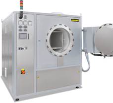 |
| Retort furnace NRA 25/09 | Retort furnace NRA 150/09 with controls H1700 and bayonet door lock |
 Vacuum pump
for cold evacuation of the retort
Vacuum pump
for cold evacuation of the retort
Basic version
- Compact housing in frame design with removable stainless steel sheets
- Controls and gas supply integrated in the furnace housing
- Welded charging supports in the retort resp. air-baffle box in the furnaces with atmosphere circulation
- Swivel door hinged on right side
- Open cooling water system
- Depending on furnace volume for 950 °C- and 1100 °C-models the control system is divided in one or more heating zones
- Furnace temperature control with measurement outside the retort
- Gas supply system for one non-flammable protective or reaction gas with flow meter and magnetic valve
- Port for vacuum pump for cold evacuation
- Operation under vacuum up to 600 °C with optional single-stage rotary vane pump
- Defined application within the constraints of the operating instructions
- NTLog Basic for Nabertherm controller: recording of process data with USB-flash drive
Additional equipment
- Upgrade for other non-flammable gases, H2 version for flammable gases
- Automatic gas injection, including MFC flow controller for alternating volume flow, controlled with process control H3700, H1700
- Vacuum pump for evacuating of the retort up to 600 °C, attainable vacuum up to 10-5 mbar subject to selected pump
- Indirect cooling
- Direct cooling
- Heat exchanger with closed-loop cooling water circuit for door cooling
- Measuring device for residual oxygen content
- Door heating
- Temperature control as charge control with temperature measurement inside and outside the retort
- Retort, made of 2.4633 for Tmax 1150 °C
- Process control and documentation via VCD software package or Nabertherm Control Center (NCC) for monitoring, documentation and control
|
|
|
Retort furnace NRA 400/03 IDB with thermal post combustion system |
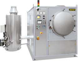
IDB Version for Debinding under Non-flammable Protective Gases or for Pyrolysis Processes
The retort furnaces of the NR and NRA product line are perfectly suited for debinding under non-flammable protective gases or for pyrolysis processes. The IDB version of the retort furnaces implements a safety concept by controlled inerting the furnace chamber with a protective gas. Exhaust gases are burned in a termal post combustion. Both the purging and the torch function are monitored to ensure a safe operation.
- Process control under monitored overpressure
- Process control H1700 with PLC controls and graphic touch panel for data input
- Monitored gas pre-pressure of the process gas
- Bypass for safe flushing of furnace chamber with inert gas
- Thermal post combustion of exhaust gases
|
|
|
Retort furnace NRA 300/09 H2 for heat treatment under hydrogen |

H2 Version for Operation with Flammable Process Gases
When a flammable process gas like hydrogen is used, the retort furnace is additionally equipped with the required safety technology. Only certified and industry proven safety sensors are used. The furnace is controlled by a fail-safe PLC control system (S7- 300F/safety controller).
- Supply of flammable process gas at controlled overpressure of 50 mbar relative
- Certified safety concept
- Process control H3700 with PLC controls and graphic touch panel for data input
- Redundant gas inlet valves for hydrogen
- Monitored pre-pressures of all process gases
- Bypass for safe flushing of furnace chamber with inert gas
- Torch for thermal post combustion of exhaust gases
- Emergency flood container for purging the furnace in case of failore
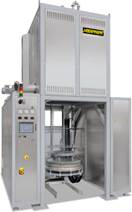 |
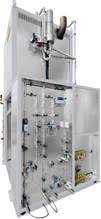 |
| Bottom loading retort furnace LBR 300/11 H2 with safety technology for operation with Hydrogen as process gas | Gas management system at bottom loading retort furnace LBR 300/11 H2 |
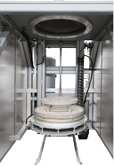
The bottom loading retort furnaces of the LBR series are suitable for production processes that are carried out in protective/reaction gas atmosphere. With regard to the basic performance data, these models are constructed like the SR models. Their size and design with electro-hydraulically driven lifting bottom make it easier to load heavy duties. The retort furnaces are available in different sizes and designs.
Basic version (all models)
- Tmax 650 °C, 950 °C or 1100 °C
- Frame-mounted housing with stainless steel sheets
- Charging from the front
- Electro-hydraulically driven furnace bottom
- Gas supply system for a non-flammable protective gas or reaction gas with flow meter and solenoid valve
- Temperature control designed as furnace chamber control
- Connection possibility for an optional vacuum pump (cold evacuation or operation up to 600 °C under vacuum)
- Defined application within the constraints of the operating instructions
- NTLog Basic for Nabertherm controllers: recording of process data with USB flash drive
- Additional equipment, H2 version and IDB version see models NR and NRA
 |
| Retort furnace SVHT 9/24-W with tungsten heating |
 Graphite
heating module
Graphite
heating module
 Cylindrical
retort with tungsten heating
Cylindrical
retort with tungsten heating
 Cooling
water distribution
Compared with the VHT models (page 64 ff), the retort furnaces
of the SVHT product line offer improved performance data with regard to
achievable vacuum and maximum temperature. Due to the design as pit-type
furnace with tungsten heating, processes up to max. 2400 °C even in high vacuum
can be implemented with retort furnaces of the SVHT..-W product line. Retort
furnaces of the SVHT..-GR product line with graphite heating, also in pit-type
design, can be operated in an inert gas atmosphere even up to max. 3000 °C.
Cooling
water distribution
Compared with the VHT models (page 64 ff), the retort furnaces
of the SVHT product line offer improved performance data with regard to
achievable vacuum and maximum temperature. Due to the design as pit-type
furnace with tungsten heating, processes up to max. 2400 °C even in high vacuum
can be implemented with retort furnaces of the SVHT..-W product line. Retort
furnaces of the SVHT..-GR product line with graphite heating, also in pit-type
design, can be operated in an inert gas atmosphere even up to max. 3000 °C.
- Standard sizes with a furnace chamber of 2 or 9 liters
- Designed as pit-type furnace, charged from above
- Frame construction with inserted sheets of textured stainless steel
- Dual shell water-cooled stainless steel container
- Manual operation of process gas and vacuum functions
- Manual gas supply for non-combustible process gas
- A step in front of the retort furnace for an ergonomic charging height
- Retort lid with gas-charged shock absorbers
- Controls and switchgear as well as gas supply integrated in furnace housing
- Defined application within the constraints of the operating instructions
- Further standard product characteristics see description for standard design of VHT models
Heating Options
SVHT ..-GR
- Applicable for
processes:
- Under protective or reaction gases or in the vacuum up to 2200 °C under consideration of relevant max. temperature limits
- Under inert gas argon up to 3000 °C
- Max. vacuum up to 10-4 mbar depending on the type of pump used
- Heating: graphite heating elements in cylindrical arrangement
- Insulation: graphite felt insulation
- Temperature measurement by means of an optical pyrometer
SVHT ..-W
- Applicable for processes under protective or reaction gases or in vacuum up to 2400 °C
- Max. vacuum up to 10-5 mbar depending on the type of pump used
- Heating: cylindrical tungsten heating module
- Insulation: tungsten and molybdenum radiant plates
- Optical temperature measurement with pyrometer
- Additional equipment such as automatic process gas control or design for the operation with flammable gases incl. safety system see VHT models
 |
| Retort furnace VHT 500/22-GR H2 with CFC-process box and extension package for operation under hydrogen |
 Graphite
heating chamber
Graphite
heating chamber
 Molybdenum
or tungsten heating chamber
Molybdenum
or tungsten heating chamber
 Molybdenumdisilicide
heater and fiber insulation
The compact retort furnaces of the VHT product line are
available as electrically heated chamber furnaces with graphite, molybdenum,
tungsten or MoSi2 heating. A wide variety of heating designs as
well as a complete range of accessories provide for optimal retort furnace
configurations even for sophisticated applications.
The vacuum-tight retort allows heat treatment processes either
in protective and reaction gas atmospheres or in a vacuum, subject to the
individual furnace specs to 10-5 mbar. The
basic furnace is suited for operation with non-flammable protective or reactive
gases or under vacuum. The H2 version
provides for operation under hydrogen or other flammable gases. Key of the
specification up is a certified safety package providing for a safe operation
at all times and triggers an appropriate emergency program in case of failure.
Molybdenumdisilicide
heater and fiber insulation
The compact retort furnaces of the VHT product line are
available as electrically heated chamber furnaces with graphite, molybdenum,
tungsten or MoSi2 heating. A wide variety of heating designs as
well as a complete range of accessories provide for optimal retort furnace
configurations even for sophisticated applications.
The vacuum-tight retort allows heat treatment processes either
in protective and reaction gas atmospheres or in a vacuum, subject to the
individual furnace specs to 10-5 mbar. The
basic furnace is suited for operation with non-flammable protective or reactive
gases or under vacuum. The H2 version
provides for operation under hydrogen or other flammable gases. Key of the
specification up is a certified safety package providing for a safe operation
at all times and triggers an appropriate emergency program in case of failure.
Alternative Heating Specifications
In general the following variants are available wit respect to the process requirements:VHT ../..-GR with Graphite Insulation and Heating
- Suitable for processes under protective and reaction gases or under vacuum
- Tmax 1800 °C , 2200 °C or 2400 °C (VHT 40/.. - VHT 100/..)
- Max. vacuum up to 10-4 mbar depending on pump type used
- Graphite felt insulation
VHT ../..-MO or VHT ../..-W with Molybdenum or Tungsten Heating
- Suitable for high-purity processes under protective and reaction gases or under high vacuum
- Tmax 1200 °C, 1600 °C or 1800 °C (see table)
- Max. vacuum up to 10-5 mbar depending on pump type used
- Insulation made of molybdenum rsp. tungsten radiation sheets
VHT ../..-KE with Fiber Insulation and Heating through Molybdenum Disilicide Heating Elements
- Suitable for processes under protective and reaction gases, in air or under vacuum
- Tmax 1800 °C
- Max. vacuum up to 10-2 mbar (up to 1300 °C) depending on pump type
- Insulation made of high purity aluminum oxide fiber
- Only fiber materials are used which are not classified as carcinogenic according to TRGS 905, class 1 or 2
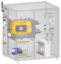 |
 |
| Schematic presentation of a cold-wall retort furnace with additional equipment 1 Retort 2 Heating 3 Insulation 4 Gas management system 5 Vacuum pump 6 Cooling water distribution 7 Controls 8 Integrated switchgear 9 Heating transformer 10 Charging frame inside the inner process chamber | Retort furnace VHT 8/16‑MO with automation package |
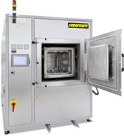 Retort
furnace VHT 100/16‑MO with automation package
Retort
furnace VHT 100/16‑MO with automation package
Basic version
- Standard furnace sizes 8 - 500 liters
- Water-cooled retort made of stainless steel
- Frame made of stable steel profiles, easy to service due to easily removable stainless steel panels
- Housing of the VHT 8 model on castors for easy repositioning of furnace
- Cooling water manifold with manual tap, automatic flow monitoring, open-loop cooling water system
- Adjustable cooling water circuits with flowmeter and temperature indicator and overtemperature protection
- Switchgear and controller integrated in furnace housing
- Process control with controller P470
- Over-temperature limiter with adjustable cutout temperature for thermal protection class 2 in accordance with EN 60519-2
- Manual operation of the process gas and vacuum functions
- Manual gas supply for one process gas (N2 , Ar or non-flammable forming gas) with adjustable flow
- Bypass with manual valve for rapid filling or flooding of furnace chamber
- Manual gas outlet with overflow valve (20 mbar relative) for over-pressure operation
- Single-stage rotary vane pump with ball valve for pre-evacuating and heat treatment in a rough vacuum to 5 mbar
- Pressure gauge for visual pressure monitoring
- Defined application within the constraints of the operating instructions
 |
| Retort furnace VHT 40/22-GR with motor-driven lift door and front frame for connection to a glovebox |
 Heat
treatment of copper bars under hydrogen in retort furnace VHT 8/16-MO
Heat
treatment of copper bars under hydrogen in retort furnace VHT 8/16-MO
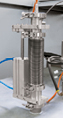 Thermocouple,
type S with automatic pull-out device for precise control results in the low
temperature range
Thermocouple,
type S with automatic pull-out device for precise control results in the low
temperature range
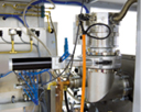 Turbo-molecular
pump
Turbo-molecular
pump
Additional equipment housing/heater
- Housing, optionally divisible, for passing through narrow door frames (VHT 8)
- Lift door
- Individual heating concepts
Additional equipment gas management system
- Manual gas supply for second process gas (N2, Ar or non-flammable forming gas) with adjustable flow and bypass
- Mass flow controller for alternating volume flow and generation of gas mixtures with second process gas (only with automation package)
- Inner process box made of molybdenum, tungsten, graphite or CFC, especially recommended for debinding processes. The box is installed in the furnace with direct gas inlet and outlet and provides for better temperature uniformity. Generated exhaust gases will be directly lead out the inner process chamber during debinding. The change of gas inlet pathes after debinding results in a clean process gas atmosphere during sintering.
Additional equipment vacuum
- Two-stage rotary vane pump with ball valve for pre-evacuating and heat-treating in a fine vacuum (up to 10-2 mbar) incl. electronic pressure sensor
- Turbo molecular pump with slide valve for pre-evacuation and for heat treatment in a high vacuum (up to 10-5 mbar) including electronic pressure sensor and booster pump
- Other vacuum pumps on request
- Partial pressure operation: protective gas flushing at controlled underpressure (only with automation package)
Additional equipment cooling
- Heat exchanger with closed-loop cooling water circuit
- Direct cooling
Additional equipment for controls and documentation
- Charge thermocouple with display
- Temperature measurement at 2200 °C models with pyrometer in the upper temperature range and thermocouple, type C with automatic pull-out device for precise control results in the low temperature range (VHT 40/..-GR and larger)
- Automation package
with process control H3700
- 12" graphic touch panel
- Input of all process data like temperatures, heating rates, gas injection, vacuum at the touch panel
- Display of all process-relevant data on a process control diagram
- Automatic gas supply for one process gas (N2, argon or non-flammable forming gas) with adjustable flow
- Bypass for flooding and filling the chamber with process gas controlled by the program
- Automatic pre- and post programs, including leak test for safe furnace operation
- Automatic gas outlet with bellows valve and overflow valve (20 mbar relative) for over-pressure operation
- Transducer for absolute and relative pressure
- Process control and documentation via VCD software package or Nabertherm Control Center (NCC) for monitoring, documentation and control
|
|
|
|
Single-stage rotary vane pump for heat treatment in a rough vacuum to 5 mbar |
Two-stage rotary vane pump for heat treatment in a vacuum to 10-2 mbar |


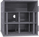
Graphite inner process chamber incl. charge holder
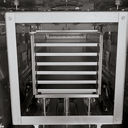
Molybdenum inner process chamber incl. six charge supports
Process Box for Debinding in Inert Gas
Certain processes require charges to be debinded in non-flammable protective or reactive gases. For these processes we fundamentally recommend a hot-wall retort furnace (see models NR .. or SR ..). These retort furnaces can ensure that the formation of condensation will be avoided as throughly as possible.
If there is no way to avoid the escape of small amounts of residual binder during the process, even in the VHT furnace, the retort furnace should be designed to meet this contingency.
The furnace chamber is equipped with an additional process box that has a direct outlet to the exhaust gas torch through which the exhaust gas can be directly vented. This system enables a substantial reduction in the amount of furnace chamber contamination caused by the exhaust gases generated during debinding.
Depending on the exhaust gas composition the exhaust gas line can be designed to include various options.
- Exhaust gas torch for burning off the exhaust gas
- Condensation trap for separating out binding agents
- Exhaust gas post-treatment, depending on the process, via exhaust gas washer
- Heated exhaust gas outlet to avoid condensation deposits in the exhaust gas line
 |
 |
| Retort furnace VHT 100/15-KE H2 with fiber insulation and extension package for operation under hydrogen, 1400 °C | Retort furnace VHT 40/16-MO H2 with hydrogen extension package and process box |
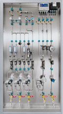 Gas
management system
Gas
management system
H2 Version for Operation with Hydrogen or other Reaction Gases
In the H2 version the retort furnaces can be operated under hydrogen or other reaction gases. For these applications, the systems are additionally equipped with the required safety technology. Only certified and industry proven safety sensors are used. The retort furnaces are controlled by a fail-safe PLC control system (S7-300F/safety controller).- Certified safety concept
- Automation package
- Redundant gas inlet valves for hydrogen
- Monitored pre-pressures of all process gases
- Bypass for safe purging of furnace chamber with inert gas
- Pressure-monitored emergency flooding with automated solenoid valve opening
- Electrically heated or gas-fired exhaust gas torch for H2 post combustion
- Atmospheric operation: H2-purging of retort starting from room temperature at controlled over pressure (50 mbar relative)
Additional equipment
- Partial pressure operation: H2 flushing at underpressure in the retort starting from 750 °C furnace chamber temperature
- Inner process hood in the retort for debinding under hydrogen
- Process control and documentation via Nabertherm Control Center (NCC) for monitoring, documentation and control